
")
")
1,3 Ghz PIC 16F84 Frequency Counter


- Details
- Category: Strumentazione
- Published on Thursday, 20 December 2012 14:08
- Written by Luigi
- Hits: 15848
Build 1,3 Ghz Frequeny Counter
using PIC 16F84
This project use a Microchip
family microcontroller PIC 16F84 as counter and the prescaler U664 as
frequency divider.
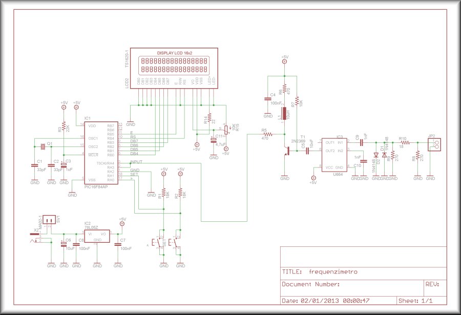
.: THE CIRCUIT :.
The schematic diagram is very
simple due PIC work that make all function. It needs only a little
amplifier stage that grow input signal from 200-300 mV p.p. to 3 volts
p.p. This is necessary to let RA4 (pin 3 of 16F84) to commute. This
input is equiped with Schmitt trigger and don't need a sharp squaring
of input signal. So it is possible to use a simple 2N2369 in common emitter
configuration, with an inductor as collector load for frequency
compensation.
With this configuration the required gain is the same from 100 KHz to about 50 MHz. Lower limit is due to value of C10 and can be modified to low value increasing C10 value.
The polarising resistor R8 is calculated to obtain 1,6-1,8 V on transistor collector and this value is needed to let the counter work properly and it can be verified before insert microcontroller in socket.
Time base is due to 4 MHz crystal. Who want more accurate mesurement can replace C1with capacitor trimmer and ajust it with a frequency counter.
Voltage regulator is 78L05 and it can be right choise for frequency counter. If you use LCD with a backlight, it will be replaced with 7805, to work properly with requested current (about 60mA).
Power supply rang is from 8 to 12 volts.
Trimmer R15 can modify LCD display contrast.
.: PART LIST :.
| -
R1 - R2 - R4 18 Kohm - R3 22 Kohm - R5 - R6 470 ohm - R7 - 10 Kohm - R8 - R9 270 ohm - R10 18 ohm - R11 3,9 Kohm - R12 1 Kohm - R13 100 ohm - R14 22 ohm - R15 trimmer 10 Kohm - T1 - T2 2N2369 |
- IC1 PIC16F84AP - IC2 78L05Z - IC3 U664 - L1 10 uH - Display LCD 16x2 - D1 - D2 1N4148 - C1 - C2 33pF - C3 1uF 16V - C4 - C7 - C8 100nF - C5 - C6 10nF - C9 - C10 1nF - C11 4,7uF 16V - XTAL 4 Mhz |
.: SCHEMATICS :.
.: PCB :.
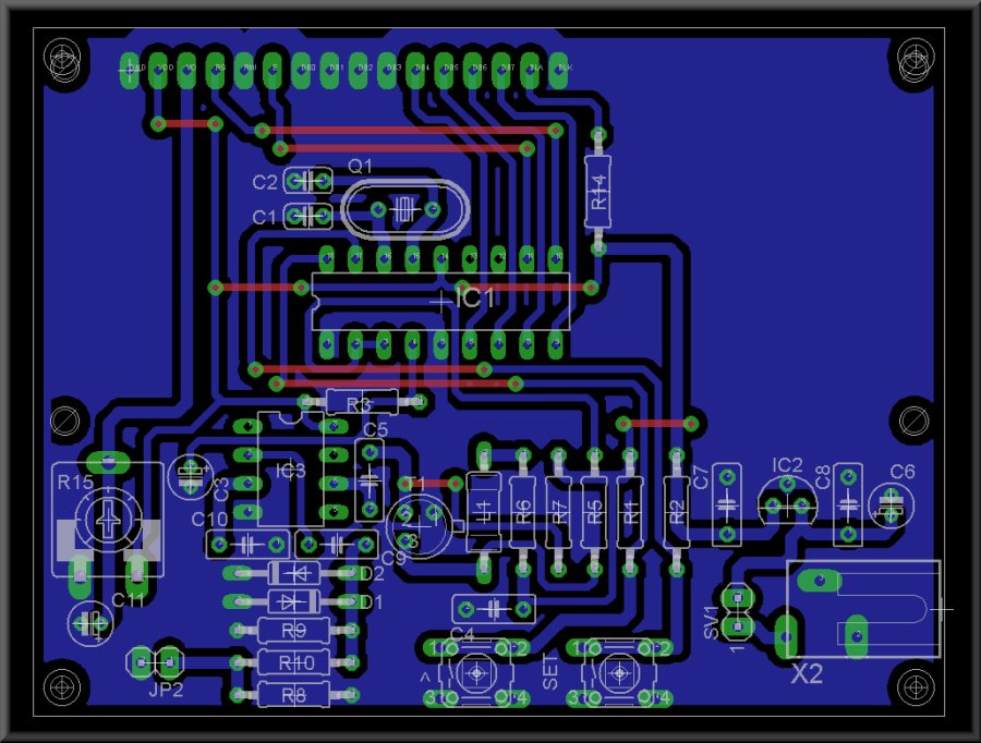
Image show component layout in
the Frequency Counter PCB.
.: 3D BOARD :.
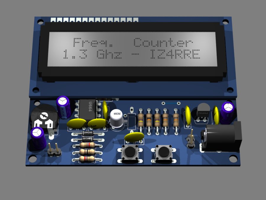
This is a Eagle3d
creation of counter.
Below you can find for download, in PDF format, schematics, PCB, comonent layout and component list.
If you need ready ti use PCB, please contact me for further details to obtain it.
Below you can find for download, in PDF format, schematics, PCB, comonent layout and component list.
If you need ready ti use PCB, please contact me for further details to obtain it.
Warning!!!
the right side to expose PCB is the side that let read the
text string.
Before print the PCB, please note that the correct scale factor (1:1) in adobe reader is selected.
Before print the PCB, please note that the correct scale factor (1:1) in adobe reader is selected.
| SCHEMATICS | PCB | LAYOUT | FIRMWARE |